
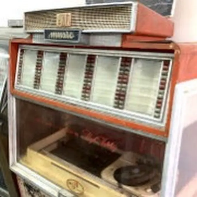
Power Supply Testing & Repair Of A Rock Ola 490 Jukebox - Motors Won't Turn
877 Video Views·May 13, 2025
Have A Question About Repairing YOUR Jukebox? Join Our Patreon Account For Direct One On One Repair Tips And Advice, Repair Tips And Clips, And Unreleased Footage!
https://patreon.com/JoesClassicVideoGames
This Is the power supply used in the 490, 494, 496 jukeboxes. Very similar to the one that mounts in the bottom of the cabinet too on later models.
ladies and gentlemen this is Joe's
classic video games back with another
cool jukebox repair video for you today
we have been working on this rockola 490
jukebox and uh it's the Super Sound to
so this is the
49-2 I
believe uh we've done a bunch of videos
on these in the past and people seem to
enjoy them because there's not a ton of
information out there about this
particular model box and it kind of gets
a bad rep because uh it had this uh
control unit in it the system 2 control
unit it was only used
in I think the
490 the 494 something like that just a
couple boxes and then uh by the time
they got to the
498 or something like that they moved on
to another uh control
unit but they sold a ton of these things
and a lot of them are broken so I wanted
to show you a little issue that's going
on with this one and we're going to
attempt to repair it we get a lot of
people emailing us and asking us
questions about these and calling us
because they've got one they're trying
to work on so I'm going to show you kind
of what one's doing and what we think
might be the problem and what you can
look at on yours and how you might get
it working so this particular one when I
plug it
in just give you an idea of
what to look for and what's going on if
I try to scan
it I don't get any kind of scan action I
do get the turntable moving which is
something that tells you something okay
we're going to slide this back to off
okay and if I go to
operate it's trying it should be trying
to go back to home position and it's not
the turntable's barely trying to move uh
there's some stuff going on right so let
me show you what to do if you if you end
up with one in a similar
situation okay the first thing you want
to check is to see if all of your LEDs
are on on the power supply so if you've
got an earlier model of the
490 it will have a slightly different
power supply in it this particular one
is the
54920 D
A and the reason that it's in this one
is because like I said it's the 490 D2
so there is a 490 a rockola 4901 and a
rockola
4902 they sold so many of them that they
redesign the entire power supply kind of
right in the middle of the Run Okay so
this one is the one that's in the later
models so you want to see but if you've
got the earlier one I believe it has a
more of a a more horizontal thing up
here this is the
amplifier um but it has a power
distribution center uh that has a uh a
little board on it with the LEDs on it
so you want to make sure all the LEDs
are on if one of them is off that's
probably your issue now if one of them
uh is off it's possible that it actually
works and the LED is just burn out but
that's um you know I'm just giving you a
place to look right if you search the
internet for the schematics for a
rockola 490 they are out there you can
download them for
free if it's the 4901 or the
4902 like this one if it's the original
490 I can't find those um schematics so
if somebody has some scan them and mail
them to me uh but there there is the the
rockola
484 schematics which are which is from a
year or two before this that has that
older style power supply in it um those
schematics are floating around so
depending on which one you got you need
to kind of look and see if it lines up
right so you're going to have to get
your hands dirty a little bit to work on
these though okay so you want to see if
all of those power lights are on however
there are a couple more voltages that
come out of this thing that they don't
have an LED for so it could be that
these four are working but you have a
couple more that are missing I'll show
you that on the schematics here in a
minute so you want to see if that's
working you want to look at your your uh
board up here without that working
your system two control unit
working the the turntable and all of
this will never scan okay so let
me I can't put this on right now because
of our battery set up basically we're
not going to deal with this in the in
this video because this system here is
actually working we're going to deal
with the power supply and the mech board
okay um but basically if you look up at
the top it tells you what those lights
mean the left light mean standard
pricing special bonus pricing lock in
pricing default pricing and then there's
one that says normal Al
operation okay now when I turn this
thing
on if I can get Focus
back I'm going to turn it off and back
on and watch what the light
does I'm going try to without knocking
the power brick out of the
machine all
right we're just watching the light
people
see the one at the bottom
right and then see how it went
off
okay let me get my focus
right so when you first apply power to
it it's saying initializing lock in that
light is on and this light is on over
here where it says standard ring okay
and so those stay on and then after a
few seconds they both turn off and on
ours this one one comes on where it says
default pricing yours may come over to
normal operation the reason that ours
doesn't go to normal operation is
because we don't have a battery
installed so we haven't saved the um the
pricing in it to the point where it can
move over to that but by the act of it
turning this light off turning that
light off and then turning that light on
what that tells you is that the board is
actually working it may not be working
fully but it's at least running the code
and it's booting up so if yours isn't
doing that and this light's staying on
or that light stay on you've got a
problem with your with your control unit
if you've got a problem with your
control unit you might be in trouble
because you're going to have to fix it
yourself
basically there's nobody around that
repairs them that I'm aware of there may
be somebody but not that I'm aware of um
luckily all of the chips on that board
are socketed there's a front board and a
backboard if you've got a couple of them
you might be able to swap the boards
around and see you could order a new
chip for every board every chip wanted
if you
wanted you know you have to deal with
that but we're not going to get into
that too much in this video because I
actually have a working one in there I
also have a working power supply but as
you can see with the working board and
the working power
supply I can't get the basket to
turn right we're at we're stuck on a
record we're at uh record 190 or
something like that okay so what's going
on I get people emailing me about this
constantly
constantly okay let me show you the
first thing that you need to
check all right there are two Motors
that do two different things or three
motors actually on this setup right now
rockola setup didn't change much over
the years it's very similar no matter
which rockola you have but this is
specifically for a rockola 490 or a
494
um this is the
cam okay so this unit spins whenever
this is
improper whenever it's working
properly all right
so there is a switch or four switches
here that change State depending on
where this cam is right and when this
cam turns it turns the gears and makes
the arm move and all that crap right
makes the gripper arm uh function all
right it can only be in one of two
states it can be where the mechanism
board is trying to control the gripper
arm which is in charge of grabbing a
record spinning it around and laying it
on the turntable and then picking the
record back up spinning it around and
laying it back in the
basket it it can do that or it can move
the me it can move the uh the
basket right it can't do both because if
it could you'd break all the records so
let's say that it's coming down and the
record and then the basket starts starts
moving well it would break the record
right or it would put it in the wrong
spot because the basket moved while it
had the record here so once so basically
there is a motor that turns the basket
around to the to the correct spot once
it gets to the correct
spot it
stops and then and only then it allows
the gripper arm uh to grab the record
and set it on the record player once the
gripper arm starts moving what happen
happens is this little switch right here
on the top this one which is switch
number one they call it there is a
little Groove down in
there that that switch has fallen into
to allow it to open see how the roller
is down in a hole there let me brighten
it up a little bit so you can see it
even
better I'm trying to be as thorough as I
can on several of these videos so people
can see what to check on theirs see how
that roller is down in that hole if
you're not like that the basket can't
turn because it thinks that the gripper
arm is up so what happens is when the
gripper arm starts turning up this cam
turns and when it does it closes that
switch once that switch closes the
basket can't turn anymore that's part of
what turns off the power to the
basket so your basket will never turn
when you put it in scan or
operate if that switch is not open you
have to be in that
hole
okay and similarly your uh your gripper
arm will never work unless you're in
that
hole or I'm
sorry disregard that we're just talking
about the basket because that actually
changes state as that turns okay so
there are two voltages that the power
supply puts out that there is not an LED
for you wouldn't think there would be
okay well one of the voltages is this
turntable so watch when I put it in scan
the turntable starts
moving I'm going to show you why that is
here in a second there is a third motor
that only runs the turntable and it runs
off of 120 volts it plugs in right here
where it
says 120 volt AC turntable power now the
two gripper Motors are ran by 28 volts
DC and they're ran um I think it's 26
volts 26 or 28 volts and they're ran
through this mechanism board that
turntable is ran straight out of the
power supply so how do they turn it on
and
off well the CPU is doing that so if you
don't have this CPU in there you can't
get that to to do that okay let's test
that theory shall we let me turn it off
and unplug the CPU and let's see if the
turn table will turn uh without the CPU
plugged
in make sure I'm telling you the right
information okay the machine is off
we're going to unplug these two
connectors on the top which are the the
power and the signals coming out I'm
leaving this plugged in it's just
telling the display what to what to do
now let's see if the turntable will
work with that
unplug so we have the board unplugged
turntable's not on
it's trying to turn a little bit that's
some kind of capacitor thing but as you
can see it's not able to
do
anything without that plugged in okay
that's because the power supply actually
I mean the CPU actually tells the power
supply to turn on the turntable what I
figured out is that the CPU also tells
the power supply to turn on the motors
that run the basket so a lot of times
whenever
people uh email and call and say that
their Basket doesn't move they think
it's the motor it's hardly ever the
motor if you've got this problem your
motor is probably fine so I'm going to
show you in the schematics exactly
what's going
on okay so this is a little bit of the
rockola 490 schematics now we are
looking at the CPU section of you know
that control unit so the control unit is
running some
things I have a a uh
a uh plush crane in the background
making a bunch of noise so anyway this
is on the control unit that box up in
the front if yours is working properly
it's probably doing this okay so one of
the things that it can do is it can send
out and receive all these little signals
here so one of the signals that it sends
out is this run signal with a line over
it usually when there's a line over
something it means that it's active when
low so if that line there goes low then
that run signal as they call it is
active right so you can see that the
board has its way of doing it it has a
LS 174 here and that connects to a
couple things an LS 32 E3 and it runs
through a couple more things and um you
know it's it's gated with different
signals and stuff and it comes down here
and it turns on has another thing here
it turns on a transistor and blah blah
blah but whatever it can make that run
line go low okay so if it were to do
that that would be a
a low signal right that it's sending out
now I'm going to show you on the power
supply what it uses that
for okay so here is further up the
schematics they call this the rectifier
PCB assembly which is part of the power
distribution assembly so this is that
big box the power supply we were looking
at now just for to orient
you orientate you here are the LEDs that
we saw that come on whenever the power
is working right so there's two there so
if this light is
on it
is the 24 volts ac light okay if this
light is on it is the 26vt DC
light if this light is on that means the
- 28 volts DC is
working and
if that one is on it means the 5.7 volts
is working so if you've got those four
LEDs then you've got most of the
voltages but there's two more voltages
that they don't mention there's no LED
for so one of them is this look switch
to 120 volts so switched means they can
turn it on and
off and look it goes to the turntable so
our turntable did you see how it turns
on and off depending on where that
switch is right so how are they turning
that on and off
off the turntable by the way just plugs
right into there okay how are they
turning that on and off with this little
baby look at this look at this
thing this is a h11
C3 opto coupler photo opto coupler now
why in the world are they using that
it's because the way these things work
this is a little chip inside of the
power supply basic basically there is a
u like an LED inside of the thing or S I
think it's an LED uh that basically when
you when you turn it on when you turn on
that led there is a little receiver
inside of it that can tell when the LED
is on and when it's on it turns on this
connection now why do they go through
all that trouble it's because they want
to be able to control 120 volts ac which
is some
juice with just a little tiny trickle
signal over here on the other side if
they were to they would need a a you
know a straight up relay that'll switch
120 volts ac the thing would burn up and
it just it has the potential to short
the other things so that this is just an
easy way to do it right so how does this
opto coupler work well it's getting
power straight from one of the um like
it's a 12vt line it runs it through a
resistor it says it's 1.2 volts DC on
this one side and then what turns on the
other side so the LED for it to turn on
it's literally a light inside of it for
it to turn on this side has to be
connected too this side is permanently
connected to 12 volts through this 1K
resistor well what turns this side
on it's our run signal that we were just
looking at from the the
uh the PC I mean the the logic unit
control unit 2 logic 2 system 2 logic
unit right so why is that important it's
because since the turntable is turning
off and on depending on where the switch
is we know that that run Line's
working so here's the schematic of the
turntable motor which we you know we're
turning on and off on and off on and off
and the only way we're able to do that
is if the switched 120 is turned on and
off and the only way that can happen is
if that opto coupler is turned on and
off which means that the only way that
could be happening is if our run line is
being used so we know that's working
because the turntable's turning on and
off now why am i showing you this is so
you can check it on yours right leave
your CPU plugged in and see if you can
turn the turntable on and off by moving
the scan turn um scan operate off
whatever see if that turns on and off if
it does then you know at least that line
is running if the CPU is not running on
the um in that logic unit though that
you're not going to be able to get that
to work okay so then what else does that
run line do well here's the here's the
interesting one so that run line
connects to that and then it also
connects through this resistor a 1K
resistor right down to
here boom right there to that
capacitor which which is a
cross this coil which is a relay in the
power
supply okay so if that is not
connected then this relay is not pulled
in all right one side of the relay is
connected to 45 volts okay so 45 volts
is coming from over here the
Transformer right so one side of the
relay is always connected to 45 volts
but the the other
side doesn't have a connection unless
that line goes goes uh
low all right so why is that it's so
that that same run signal can turn this
relay on and off so what does the relay
do well if the relay
isn't um pulled in then you have a
normally connected situation here where
this line which is the ground from the
Transformer the center tap from the
Transformer connects to this 24volt DC
line here and basically shorts it out so
why does it do
that right I may have it backwards of
what it does when it's on or off or
whatever but basically it connects to
there um and shorts this to ground well
what that does is it makes this the
input to this lm3 17 it's getting 45
volts on one side it's getting ground
here uh and it can it's basically
turning on and off the switched 26 volts
not to be confused with the 26 volts
there's two different outputs so there's
a 26vt and a switched
26vt so there's no LED on the switched
26vt now I know this is really
confusing this switched 26vt is are you
ready for it
it's how it turns on and off the gripper
motor and the mechanism
motor so we
know that that signal works right where
are
we we know that that signal Works down
here to turn on the
relay but it's either not turning off
the relay or not turning on the relay or
something something's not right and uh
that's why you're not getting this
voltage out if you check this switched
26 volts with which is a red and blue
line coming out of the power supply and
it it goes over to the uh that switch we
were talking about on the cam on the
front of the machine if you check on
that red and blue line I'll bet you you
don't have 26 volts there and that's why
you are not getting your um that's why
you're not getting your Motors turning
so a lot of people think I think my
motor's bad and they buy new Motors
those Motors don't usually go bad
they're the like the last thing to go
bad it's much more like that some of
this Craft's going to go bad so you know
what usually goes
bad that
relay so look how they've designed it if
the relay is closed you have just
shorted this to
ground so this 24 volts isn't there
because now there's
ground uh on both sides of this
um uh xener diode
here 24 volt diode so it basically takes
it out of the equation
if that's open now you've got the xener
diode in play and it raises this up to
24 volts because it's using it it's
basically using the output of the uh the
voltage regulator there and all this
it's an adjustable voltage
regulator right so if this if this
little relay is bad that's going to
cause you all kinds of problems that's
what's wrong with mine I believe so
here's the next okay so if if that does
pull in it can also send ground
to this connection so what does it do
well if you look on the schematics see
the line going up
there it connects up to
here which it
calls audio
control so it says audio system socket
it's probably something that turns on or
mutes the um mutes the Jukebox or turns
on the Juke box there I mean not the
Jukebox The
Amplifier
right so why would they do that well
once the gripper arm is doing its thing
and it's in this position where it's
supposed to be or whatever maybe I'm
just guessing maybe the the um control
unit turns off the motors the power to
the gripper arm and the power to
the the uh basket and turns on the power
to the output of the amplifier that's
why it's all muted until the record
starts playing and then you hear it pop
on that's what I think that's probably
how they're doing it okay so all of that
to say if you're if that that's some
things to check and the order to check
them in to try to tell what's wrong with
yours right so if you don't understand
exactly what I was saying go back and
watch through the video and maybe you'll
catch what I'm talking about you want to
check your power supply you want to
check the lights on your on your logic
control unit you want to check to see if
the turntable turn turns and turns off
which is also important right because
that will tell you if this run line is
working and then finally you want to
check the output this voltage here and
see if your switch 26 volts is going out
on the red and blue line coming out of
the power supply if you if that never
comes on then of course your your uh
Motors aren't
running because you don't have the
voltage for them to run so let me show
you what the mechanism board does with
that voltage so the power cable comes
down here and it plugs into that board
in the front I was talking about which
is the mechanism power board okay now
depending on which version of the of the
machine you have that thing actually may
actually be on the back but it'll say
mechanism powerboard right on it right
there's a couple different designs like
I said there's a little six pin
connector that plugs in okay and so one
of them is a signal that's called cam
one I think that may be actually a
signal back to the the board uh there's
a there's a um
a home
switch signal here now that's basically
so it can tell when it gets back to the
home
position there is an A and B and then
look here's our 29 they're calling it 29
volts at this point 29 volts DC switched
it's that same red and blue wire and it
plugs in at Pin five right so if you
look on here pin five on the actual
board comes
down and it goes all around and it comes
up here and boom it goes to the fuse so
if that fuse is blown of course the
board can't use any of the power but
that's how the power gets on the board
the way they turn off the um the motors
is they can be completely turned off by
the power supply which is turned off by
the
um
um it's turned off by the CPU now I was
just thinking since they use the same
line to make the uh um to make the
turntable turn on they can't turn off
the the motor the power to the U Motors
if they have the turntable turned on
right maybe the turntable has another
way of getting power or
something um okay and then there's a few
switches I'll show you two on that Cam
that can turn things on and off okay so
we finally made it to the motors the
magazine motor and the gripper motor so
you see like if we're looking at the
magazine motor so I can't get it to turn
right now one side of it and the gripper
motor is connected to a red and white
wire which comes off of the mech board
right and then the other side the
magazine motor gets its power through
the pink and blue wire that is connected
through that switch number one that I
was talking about right so this switch
if it's down in that
hole uh the basket can get
power the magazine motor as they call it
and then if it's out of that hole it
connects back this
way which sends the power up this way to
P five blah blah blah blah and does some
other tricky stuff
right so that's what you need to look at
so um I'm interested now in how the
um when it would turn off the magazine
power I guess it would just turn it off
whenever it's also going to turn off the
[Music]
turntable yeah so there's there must
still be voltage on that
line oh yeah it has to be so there has
to still be voltage to the mech board
while the turntable's Turning because it
still needs to be ready to hang up the
reverse the uh uh everything and hang it
all back up run the motors in reverse
and all of that so it the actual uh
gripper motor goes both ways it has to
lay it down and then it has to pick it
back up again too and put it back in the
basket so it has to run either way so
they have a
little um setup down here where they
make it go backwards how does that
work pin
seven a reverse relay it seems
to reroute some of the signals to make
the power go to one side or the other
all right so anyway all that to say I
think that relay is bad on my powerboard
so I've ordered one but guess what you
can't get the one that's on the actual
power supply they're obsolete apparently
this is a problem that people are
running into in all kinds of vintage
audio equipment where they use these
little relays that you can't get anymore
and so the footprints different
everything on it's different so I'm I've
ordered a substitute we're going to rig
it up in the best possible way we'll
consider it an upgrade but we have to
replace that and we'll see if uh if that
gets us up and running so I'll show you
what that little board looks like uh on
the bench let's check it out okay folks
so I've got the power supply out of it
okay this is the board that we're
looking at on the
schematics there's a few capacitors in
there I want to replace so I'm going to
order those too all of the fuses are
fine um and I've got it set
up now be careful if you're messing with
this folks don't do this
now if you decide to do it you did it
against my
wishes um so the thing is you can plug
this in just uh outside of the machine
right and then check your voltages and
things from there so if I plug it in and
turn it on I've got all four of my
lights on right now those lights by the
way that doesn't necessarily mean that
the voltage is perfect it just means
that there's some kind of voltage there
okay now this is the relay that I'm
talking about
this is
a I'm going turn the camera instead of
turning the
machine it is a
Potter
Brumfield
r502
dy1 D 24v
DC so that's a 24volt relay and it's
just a one pole so it just turns goes
from one connection to another uh there
a two amp uh the the coil can handle two
amps and the one amp draw it can handle
one amp on the uh the 120 volts that can
run through the
contacts that is uh this area right here
now again if you look the normally
connected shorts over 1 in 4749 which is
a little diode okay now with the thing
turned
off
notice I have replaced that diode I've
been messing with it I messed with this
last night then I decided I better film
this with it turned off that diode is at
a direct short across it
because that's normally connected so we
need this relay to pull in and move this
away from here to here which will allow
this to pull the 24 volts or whatever
from the output to make this
output properly
okay okay folks so we've been ordering
all kinds of
Parts not all kinds just a few and I
have replaced the major capacitors the
big bigger capacitors on this little
board but our main problem we think is
with the relay so here is the relay it's
an R 50- E2 dy1 d24 volt DC this thing's
completely obsolete they haven't made it
in Forever you can't get anything that
it's even similar to it because the
footprint is
strange so these two outside ones here
are the coil 24volt coil so when 24
volts goes to that this is the
common it can it connects to this um
inside post here that's the normally
open this outside one is the normally
closed okay I'll show you a little
drawing of the
schematic
so if you can kind of tell what that is
um basically you know when the coil
pulls in it pulls it from one way till
it's connected the other way okay if I
don't drop it on the
floor so the coil if you test the
resistance across the coil it's like 700
ohms which should be fine but it just it
isn't working so it must be if it pulls
in it's not connect conting this pin to
this middle pin here it's but this pin
is connected to the top pin okay so
that's the normally closed position when
it pulls in it should change this pin to
this pin but it's not working so I
googled this thing and there are a few
of them out there they're trying to get
$200 for this thing used because
apparently it's in a lot of vintage
audio equipment which must have been
where they got the idea to use it in
this jukebox so I looked around I said
you know what I'll uh I will just order
another 24volt relay and then I'll just
wire it up and it won't be no big deal
so I looked online made sure to get one
with the right specs so this one is if
you're running one amp through
it I mean if you're running um 120 volts
ac through it uh it has 1 amp
um uh a 1 amp rating on the contacts
inside of this so you can run up to an
amp at at
125 or 120 volts ac through it but if
you're running 28 volts DC which is
pretty much what we're running this is
like what 26 volts DC you can run up to
2 amps through it right so this thing
needs to be rated for 2 amps my
replacement one so I look online and I
find one and I find one that's rated 2
amps looks pretty good I was like oh
okay let me order that so I order it's
like $2 order a couple of them it comes
in it's this little tiny
relay right look at this
thing so it's
an
axicom 1
m07 but it's rated for 2 amps at at 28
volt or I think 30 volts DC it's rated
at 2 amps so it's got the same rating
but look at it compared to the other
one and so I've looked and looked and
looked and read and read and read and I
read this data sheet and this data sheet
I think it's the same rating people it's
just really small that's not really the
best one to use though uh because it it
just it's so small that the leads are so
close together that it's harder to to to
use right but what I did was I very
carefully uh attached wires to
it and then put shrink wrap on the wires
so they wouldn't touch each other
soldered the wire to the legs and then
ran the legs down into the board
into the five holes that the original
relay used right so the two of them are
for the coil one of them is the common
and the other one is the two contacts
that switch back and forth and I got it
all wired up and I mean you know I got a
some heat shrink on it put a little zip
tie on it and everything so it can't
short out or anything it's just kind of
sitting there it's so small I mean you
could you could zip tie it to something
else this is not really the best one to
use I I wish I had a bulkier one so I
may I may order one that's bulkier but
it is rated the same so technically it
should
work okay so how are we going to test it
well on the
schematics it's got that run
signal Illustrated
right so that run line comes
in and it's basically
grounding this up here which is the the
uh um optocoupler we were talking about
um which turns on the 120
volts and then also through this
resistor it will turn on our relay which
is this area here which will turn on our
24
volts
okay which will make our switch to 26
work right so we're going to try it now
I've got the uh multimeters hooked up on
the uh output of that let me turn it on
and we'll see what kind of voltage we
get nothing but it's all on right now if
I ground that run line to where it
thinks that the CPU is telling it to
turn on the Run
line
oh I'm on
AC that won't work there we go so I've
Got 24.8 5 volts if I turn the ground
the Run line off we have 2.4 volts
DC
okay we put it back 24 volts so it now
should be able to turn on and off the
motors very cool okay folks we've been
doing a lot of work on the machine we've
been uh working on the uh MP the control
unit uh the amp uh the mechanism the
lighting which was actually a really big
problem we had to put a a
fluorescent um a more modern ballast in
it and take all the old ballasts out and
rewire half of the stuff um if you get a
problem by the way where your
computer keeps going back to initialize
and it's doing it over and over again or
it sticks over there if you have a light
bulb that's blinking it'll make it do
stuff like that because it's screwing up
the the voltage that it needs to boot
okay but I just wanted to show you I've
got the lid carefully leaned down
here and as you can see we have that
new uh relay in there all
right so I'm going to show you what this
thing is supposed to do when you turn it
on okay just so you'll know if yours
isn't doing this okay so it's off this
is what you should get when it comes
on it move just a little bit yours may
or may not do that depending on where
it's at or that may be a capacitor thing
or something
um so you've got that and
then as it's scanning the turntable will
move because it's using that home line
that we were talking about now that
means that relay is working right put it
back in operate and then if I pick a
record now I can't play a record right
now
people but what I'll do is I'll pick up
another uh I'll do another small video
that shows one plan but as you can see
everything is working uh we already had
our our control board working so what it
ended up being uh was that relay and you
can see it's up and running in the
cabinet so if you have an issue where
you can't get anything to
turn um at all it very well could be
that line on the power supply so you
kind of need to check that and kind of a
giveaway
um well I don't you know the the
turntable
moving I don't know if it actually needs
the relay to work because it's using
that optic actually that that uh coupler
so but um there you go I hope that helps
you with
yours
check the relay I believe I've had
several that have that relay bad in it
um I've had a couple in the past that I
swapped the entire power supply out in
it and looking back I think that's what
the issue was because you'll get all of
your voltages but uh if you don't check
that switched voltage because they don't
really mention it and they don't have an
LED for it you may not know that they're
blowing me up on the phone people so I
hope you enjoyed it uh we'll we'll
upload another video of this thing
actually playing just so you can hear
what it sounds like we've got a ton more
videos on especially rockola jukebox
repair so check those out on our channel
here make sure to give us a thumbs up
for taking the trouble to film it for
you and uh leave your comments down
below now if you want to know how you
can support our channel I may have
mentioned it earlier but there are links
to Amazon down below if you're going to
buy anything on Amazon they may have
that relay on there if you're going to
buy anything on Amazon click our link
and that'll take you to Amazon and then
you can browse around and anything you
buy uh gives us a tip so we appreciate
everybody that's been doing that we will
see you on the next
video